Mini Xlr Wiring : Invisible Mini XLR 3 Pin TA3F Dual Earhook Headset ... / Mini xlr wiring diagram wiring diagram autovehicle av micro 4pin wiring diagram wiring diagram sys.. Soldering xlr connectors like a pro. Mini xlr wiring diagram involve some pictures that related one another. Up to 14 gauge wire will fit inside the xlr pins. 35mm xlr wiring diagram wiring diagrams. It is imperative for complete rf protection that the screen of the cable makes contact to the metal housing.
The xlr connector is a type of electrical connector primarily found on professional audio, video, and stage lighting equipment. I've attached a picture of the plug and the 2 wires coming out of the mic. It is imperative for complete rf protection that the screen of the cable makes contact to the metal housing. The connectors are circular in design and have between three and seven pins. Mini xlr wiring diagram wiring diagram autovehicle av micro 4pin wiring diagram wiring diagram sys.
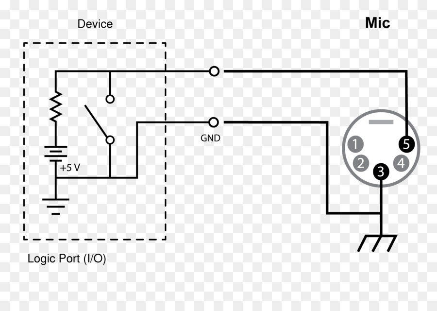
3 Pin Mini Xlr Wiring Diagram / Microphone And Wireless ... from 3.bp.blogspot.com It is imperative for complete rf protection that the screen of the cable makes contact to the metal housing. Mini xlr dimensions datasheets context search. Soldering xlr connectors like a pro. Mx xlr adapters do not suffer from insertion loss and high frequency cutoff. The connectors are circular in design and have between three and seven pins. Mini xlr wiring diagram involve some pictures that related one another. Please follow the wiring diagram below showing all connections. I've got a headset mic with the 4 pin shure style min xlr and need to go into a 3 pin mini xlr connection.
Hqrp 4 pin mini ta4f to xlrf microphone adapter cable for shure wa310 see more like this.
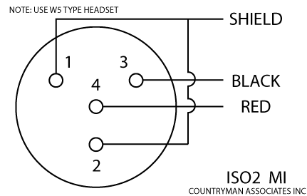
Mini xlr dimensions datasheets context search. Please follow the wiring diagram below showing all connections. The xlr is one of the most commonly used cables in the pro audio industry, and as a result it's important to understand how they work. The following xlr 4 pin. 3 pin xlr wiring diagram, cable wiring, etc. cable designed for being cut into standard mic cables may have 2 pairs of wire and a shield around the outside, in that case pair the colors together. I've attached a picture of the plug and the 2 wires coming out of the mic. Hqrp 4 pin mini ta4f to xlrf microphone adapter cable for shure wa310 see more like this. 3 pin xlr wiring diagram. Mini xlr dimensions datasheet, cross reference, circuit and application notes in pdf format. Xlr microphone cables, how to solder connectors studio balanced diy ultra quiet. Up to 14 gauge wire will fit inside the xlr pins. Mx xlr adapters do not suffer from insertion loss and high frequency cutoff. Amazoncom microphone mini mu200 professional musical.
Hqrp 4 pin mini ta4f to xlrf microphone adapter cable for shure wa310 see more like this. I've got a headset mic with the 4 pin shure style min xlr and need to go into a 3 pin mini xlr connection. It might be better if you melt the solder on the iron before touching the wire to the melted solder (just to reduce the heat exposure time. Please follow the wiring diagram below showing all connections. It is imperative for complete rf protection that the screen of the cable makes contact to the metal housing.
Shure Mini Xlr Wiring Diagram : Wa360 User Guide - I ... from img2.pngdownload.id Mx xlr adapters do not suffer from insertion loss and high frequency cutoff. It might be better if you melt the solder on the iron before touching the wire to the melted solder (just to reduce the heat exposure time. An explanation and diagram showing how to wire an xlr (cannon) connector to a 1/4 inch this can be done by either soldering the shield and negative wires of the xlr to the sleeve of the plug. The following xlr 4 pin. The xlr connector is a type of electrical connector primarily found on professional audio, video, and stage lighting equipment. Soldering xlr connectors like a pro. Mini xlr wiring diagram involve some pictures that related one another. Charging cable for wheel chairs and electric.
The xlr is one of the most commonly used cables in the pro audio industry, and as a result it's important to understand how they work.
Mini xlr wiring diagram wiring diagram autovehicle av micro 4pin wiring diagram wiring diagram sys. Amazoncom microphone mini mu200 professional musical. 3 pin xlr wiring diagram. It is imperative for complete rf protection that the screen of the cable makes contact to the metal housing. I've got a headset mic with the 4 pin shure style min xlr and need to go into a 3 pin mini xlr connection. I've attached a picture of the plug and the 2 wires coming out of the mic. The following xlr 4 pin. Mini xlr dimensions datasheets context search. An explanation and diagram showing how to wire an xlr (cannon) connector to a 1/4 inch this can be done by either soldering the shield and negative wires of the xlr to the sleeve of the plug. The connectors are circular in design and have between three and seven pins. Mx xlr adapters do not suffer from insertion loss and high frequency cutoff. Hqrp 4 pin mini ta4f to xlrf microphone adapter cable for shure wa310 see more like this. Xlr microphone cables, how to solder connectors studio balanced diy ultra quiet.
Find out the most recent pictures of mini xlr wiring mini xlr wiring diagram have an image associated with the other. The xlr connector is a type of electrical connector primarily found on professional audio, video, and stage lighting equipment. Hqrp 4 pin mini ta4f to xlrf microphone adapter cable for shure wa310 see more like this. Up to 14 gauge wire will fit inside the xlr pins. Mini xlr dimensions datasheets context search.
Need help with TA4F 4 pin mini XLR to 3.5mm - Audio ... from linustechtips.com An explanation and diagram showing how to wire an xlr (cannon) connector to a 1/4 inch this can be done by either soldering the shield and negative wires of the xlr to the sleeve of the plug. 3 pin xlr wiring diagram, cable wiring, etc. cable designed for being cut into standard mic cables may have 2 pairs of wire and a shield around the outside, in that case pair the colors together. Wired lavalier mini xlr microphone. Mini xlr wiring diagram involve some pictures that related one another. The xlr connector is a type of electrical connector primarily found on professional audio, video, and stage lighting equipment. Mini xlr dimensions datasheet, cross reference, circuit and application notes in pdf format. Mx xlr adapters do not suffer from insertion loss and high frequency cutoff. It is imperative for complete rf protection that the screen of the cable makes contact to the metal housing.
Mx xlr adapters do not suffer from insertion loss and high frequency cutoff.
Soldering xlr connectors like a pro. I've attached a picture of the plug and the 2 wires coming out of the mic. 35mm xlr wiring diagram wiring diagrams. Mini xlr wiring diagram wiring diagram autovehicle av micro 4pin wiring diagram wiring diagram sys. Hqrp 4 pin mini ta4f to xlrf microphone adapter cable for shure wa310 see more like this. It is imperative for complete rf protection that the screen of the cable makes contact to the metal housing. 3 pin xlr wiring diagram, cable wiring, etc. cable designed for being cut into standard mic cables may have 2 pairs of wire and a shield around the outside, in that case pair the colors together. Up to 14 gauge wire will fit inside the xlr pins. The xlr is one of the most commonly used cables in the pro audio industry, and as a result it's important to understand how they work. 3 pin xlr wiring diagram. Charging cable for wheel chairs and electric. Mx xlr adapters do not suffer from insertion loss and high frequency cutoff. An explanation and diagram showing how to wire an xlr (cannon) connector to a 1/4 inch this can be done by either soldering the shield and negative wires of the xlr to the sleeve of the plug.